
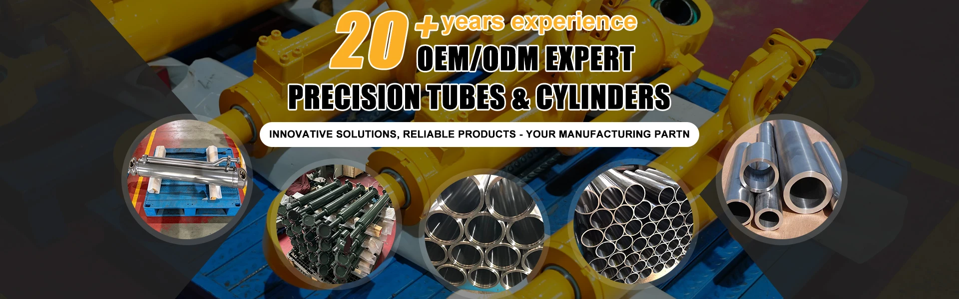
As a core component of an ESP (electric submersible pump) system, the ESP pump casing's appearance not only directly impacts the equipment's structural strength and sealing performance, but also its ease of installation and maintenance, as well as its long-term operational reliability. This article systematically describes the typical appearance characteristics of ESP pump casings, including overall appearance, surface treatment, interface design, and marking information.
Overall Appearance and Structural Layout
ESP pump casings typically adopt a cylindrical or stepped cylindrical design to fit within the wellbore annulus and optimize fluid dynamics. Their main structure is symmetrical, with a length-to-diameter ratio tailored to the required head. Lengths typically range from 30 to 150 cm, while the outer diameter is limited by the casing's inner diameter (typically 100 to 200 mm). The top and bottom of the pump casing are rigidly connected to adjacent components (such as the motor protector and suction inlet) via flanges or threaded connections. Transition areas are often designed with rounded chamfers to reduce stress concentration risks. Some models incorporate annular reinforcement ribs in the center of the casing, either through increased wall thickness or embedded metal inserts to enhance pressure resistance, making them particularly suitable for high-pressure reservoir environments.
Surface Treatment Process Characteristics
To combat downhole corrosive fluids (such as crude oil containing hydrogen sulfide and carbon dioxide) and abrasive particles, the outer surface of the pump casing typically undergoes multiple layers of protective treatment. The base layer is a matte gray-black metal substrate that has been sandblasted and derusted, resulting in a uniform metallic luster on the exposed machined surface. The protective layer typically consists of an epoxy resin coating or zinc-nickel alloy plating, with a thickness ranging from 50 to 200 microns. The surface is smooth to the touch and free of visible cracks or bubbles. Pump casings used in high-temperature and high-pressure applications may also be coated with a ceramic wear-resistant layer. This layer features regularly arranged black or tan enamel particles on the outer surface, which feels slightly rough but significantly enhances erosion resistance.
Functional Interfaces and Connection Features
The pump casing's fluid inlet and outlet are arranged in axial or radial opposition. The inlet is often designed as a wide-mouthed, trumpet-shaped flow guide with a positioning boss on the outer wall to ensure precise connection with the suction port. The outlet is often a tapered design with a smooth inner wall transition to reduce fluid turbulence. All joints feature fine-pitch threads or stepped grommets, which provide a static seal with O-ring grooves (3 to 8 mm wide). The threaded surfaces exhibit uniform milling patterns and are free of burrs. Flange connections feature four to eight evenly spaced bolt holes with chamfer radii that meet API standards, facilitating quick on-site assembly. Some intelligent pump casings integrate a pressure sensor port on the side. This area is marked with a small, circular recessed platform on the outer wall, laser-etched with a logo such as "PRESS" in the center.
Marking and Traceability Information
Permanent markings are cast on the non-working surface of the pump casing (usually the side or bottom). These include the manufacturer's trademark (e.g., SCHLUMBERGER, Baker Hughes), model code (e.g., 572 Series), material designation (e.g., ASTM A536 Grade 65-45-12), batch number, and date of manufacture (in the format YYYYMMDD). Key parameters are marked in relief or concave text, with a minimum height of 3 mm. Some high-end products utilize laser marking technology to create a dark, permanent marking. Pump casings compliant with ISO 13533 standards also feature the maximum operating pressure (e.g., 10,000 psi) and temperature rating (e.g., 150°C). These values are prominently printed in white or red ink against a dark background to ensure legibility during downhole operations.
Features Suitable for Special Operating Conditions
Pump casings designed for high-sand-content oil wells feature directional sand removal grooves (1 to 3 mm deep, 5 to 10 mm apart) on the outer wall. These grooves extend axially to the flange connection area, preventing sand accumulation and maintaining structural integrity. Corrosion-resistant pump casings feature a mirror polish (Ra ≤ 0.8 μm) on wetted surfaces (such as the outer walls of the fluid passages), while non-wetted surfaces retain a standard turning texture (Ra 3.2 to 6.3 μm) to reduce manufacturing costs. Pump casings for deepwater applications feature an external anti-fouling coating. These components exhibit a uniform matte blue or green finish that feels sticky and lacks the raw metallic texture. In summary, the appearance of the ESP pump casing is a comprehensive reflection of its functional design, materials science, and engineering practices. Through morphological optimization, surface enhancement, and standardized markings, a balance is achieved between structural strength, fluid efficiency, and service life within a limited space. These features are not only an important basis for judging equipment quality but also provide a key visual reference for on-site installation, troubleshooting, and maintenance.


